I suspect that this $4 circuit is the phase coupler sold commercially for 20 times as much. Alternatively, they can be wired right into the breaker box.
Phase coupling: The components are small enough to be built into a 2 or 3 phase plug. Electric code dictates no circuitry in breaker boxes, so build a plug, if you're a purist.
Bill of materials for each phase couple (three phase systems would need double of this):
The inductor-capacitor values are such that they resonate at the frequency of typical X-10 signals, thus allowing the X-10 signals to pass across to the other phase.
The complex impedance of a capacitor is: Z = [1/jwC]. X10 signals are sent at 120KHz. At this frequency, a 0.1uF capacitor would create an impedance of 13.2 ohm, which might hinder obtaining equal signal strength on the two phases. A larger capacitor could be used, but that is more expensive, physically larger, and increases the reactive power load on the circuit from the 2.2 VA with 0.1 uF capacitor.
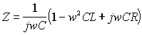
The series R-L-C circuit complex impedance is given by:
where w = 2(pi)f. The resonating frequency in which the capacitive reactive impedance is canceled is for L = 1/(Cw^2). At this value of L, the circuit impedance is purely resistive with Z = R. The circuit is tuned to resonate at the frequency.
The inductance required to bring a 0.1uF capacitor to resonance at 120 KHz is 17.6 uH. A 18uH inductance is an "off the shelf" value.
The finished
signal-bridge therefore consisted of a 0.1uF 630 V capacitor in series
with a 18uH inductor - plus a 1/4 amp fuse.
Another Noise Blocker/Filter
The X-10 noise block/filter circuit acts just the opposite as the coupler circuit in that instead of "passing: the X-10 signal, it "blocks" the X-10 signal.
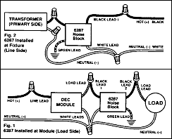
LEVITON 5 AMP X-10 AC FILTER MODEL # 6287 SCHEMATIC
----------------------------------------------------
7uH* 7uH*
BLACK ----+---))))))---+---))))))---+----
BLACK
| |
|
| | | |
| | |
-----| |-----+-----| |-----
| | | | |
|
0.22uF ----- 0.22uF
-----
| 1uF
* 12 turns #18 wire
|
on a toroidial core
/
0.5" OD
\ "FUSE" (1 strand #18 wire on PCB)
0.25" ID
/ (probably about
1 amp)
0.25" THICK
|
WHITE
A simulated response of this "notch" filter is shown below. As can be seen, it blocks well around the 120-130KHz frequencies (the frequency of typical X-10 signals):
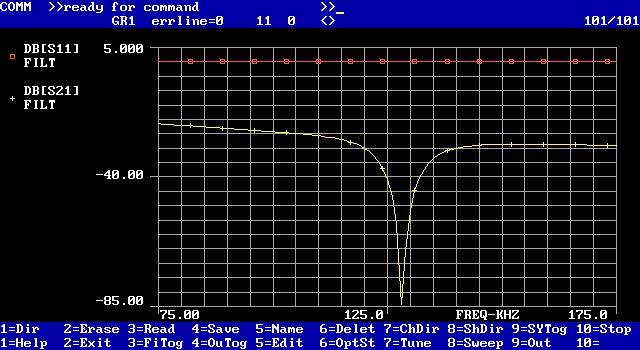
Figure 7 below
shows a noise block connected in a fixture (Line side). Figure 8 shows
a noise block connected at module (load side). Black are the live leads,
white the
neutral lead.
In both cases it couples any 120kHz signal generated by the noisy device
to ground.
 |
|
||||||||||||||
|
|
|

Earthmen
Productions
©1996-2003
