 Is
the sound of that X-10 Chime Module getting on your nerves ??
Is
the sound of that X-10 Chime Module getting on your nerves ??
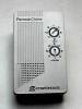
| Modifications for the X10 Chime Module |
|
Is
the sound of that X-10 Chime Module getting on your nerves ??
I have used these X-10 Chime Modules for all kinds of Notification/Alarms/Chimes, etc... When I first integrated them into my HA system, the first use was to use them as my new doorbell notification. Lucky for myself, my two (front & rear) doorbell wires were run directly to where my service panel is located. Granted, most installations usually wire the door bell in series with the 24 VAC doorbell transformer and the doorbell itself. If your doorbell is connected up in this series fashion, there is still a work around! If you are not going to use the existing door bell, you can easily connect the wires together right at the doorbell (First!, be sure to disconnect the 24 VAC bell transformer from the service panel/fuse!) The wires are also removes from the transformer and now, these wires should show continuity when the doorbell button is pressed. These wires can then be connected to your HA Controller (in my case, the Digital I/O input on my Stargate). If you have multiple doorbell pushbuttons and you try this trick, you will only have one contact closure for both doorbell button (no way to discriminate from each other).
Anyway, in my case, I had two separate contact closures, one for the
front door and one for the rear door. Now my next task was to program my
controller (Stargate) such that when the front door doorbell button was
pressed, it would trigger one Chime module and when the other rear doorbell
was pressed, it would trigger a different Chime module. Well, not really
thinking well that day, I wanted to put both of these modules upstairs
so that I could determine when a doorbell button was pressed and also,
WHICH doorbell button was pressed. Well, both Chime modules make the identical
sound (Ding Dong, Ding Dong, Ding DING!). This was lousy planning on my
part! The only thing I could do was to figure out how to make one chime
sound different from the other.
Well, this is how you do it!
(You can refer to the SC-546
Chime Module schematic for this modification)
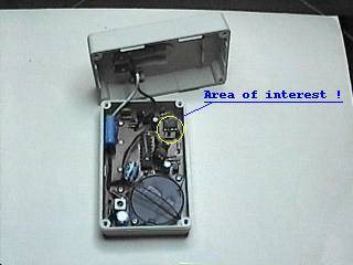
First, you must remove the 4 screws on the back 4 corners and separate
the top and bottom halves of the enclosure. After the shells are separated,
locate
the area of interest, the area where the red LED and IC are soldered.
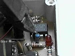
Locate the 820K resistor (mine looks blue-ish in color). This resistor
is responsible for the tone/speed of the "Ding/Dong" for the Chime module.
Increasing its resistance will decrease the speed/tone of the chime sounds
and decreasing the resistance will increase the speed/tone of the chime.
It is located just off of pin#1 and pin#2 of the 8 pin DIP (sound generator?).
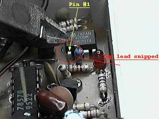
Locate the top lead of this 820K resistor. With
a pair of snippers, snip this top lead and separate
the two ends of the lead to be sure they don't touch. The left end
of the lead (now disconnected from the resistor) is connected (via PCB)
to Pin #1 of the IC. I have experimented to determine what should be the
lowest resistance. This would cause the highest possible sound/tone for
the module. I've determined that a resistance of 150K yields the highest
possible sound/tone which a human can bear (maybe you want to use a lower
resistance so you can hail your dog!). The next task was to determine the
highest resistance required to produce the lowest tone/speed setting. This
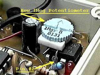
resistance was determined to be approximately 1 Meg. Therefore, I decided
to use both the 150K resistor and a 1Meg potentiometer in series, and this
would be placed across Pin#1 and Pin#2 of the IC. Seeing that the 820K
resistor was not going to be used, I thought about completely removing
it but, decided to simply fold/push it to the right towards the LED (making
certain not to short out any thing). The next step was to solder
one end of the potentiometer to Pin#2 of the IC. (If possible, use
a clip-on heat sink when soldering to any IC pin) Position the Potentiometer
on top of the IC with one lead pointing out and the other pointing down,
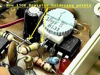
soldered to Pin #2. The next step is to connect the
150K resistor from the other potentiometer lead to the open lead (from
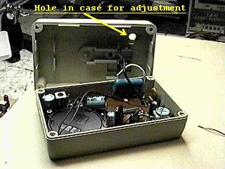
snipped resistor) leading to Pin #1 of the IC. The next thing I did
was to determine where to drill the adjustment access hole needed to adjust
the potentiometer once the enclosure is all buttoned up. I
drilled a 3/8 inch hole in the bottom half of the plastic enclosure
and reassembled the two halves of the case, replacing the four screws.
With all this completed, you are ready to test!. Position the potentiometer
to approximately 2/3 (700K ohm) its range (150K + 700K = 850K... almost
the original value of 820K!). Plug the Chime module in an outlet and test.
It should chime almost in the same speed/tone as originally designed. Now,
turn the potentiometer clock-wise to increase the tone/speed of the chime
or counter clock-wise to decrease the speed/tone of the chime.
Now, wasn't that easy !? I have 4 modules modified as such, two each for either doorbell, upstairs and down stairs.
Go to Top of Page Return to Tom's X-10 Modifications Webpage Go to Tom's X-10 Webpage |
(You can refer to the SC-546 Chime Module schematic for this modification)
Go to Top of Page Return to Tom's X-10 Modifications Webpage Go to Tom's X-10 Webpage |
(You can refer to the SC-546 Chime Module schematic for this modification)
Go to Top of Page Return to Tom's X-10 Modifications Webpage Go to Tom's X-10 Webpage |
 |
|
||||||||||||||
|
|
|
Earthmen
Productions
©1996-2004
